
Offsets
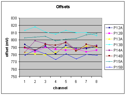
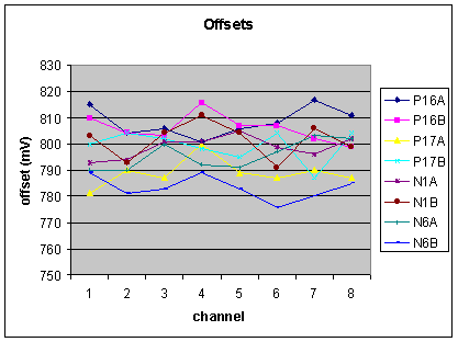
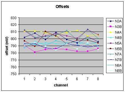
Offsets were measured on 272 channels (17 boards, 34 chips) by recording the threshold value that inverts the discriminator output signal. The following plot shows the offsets on all channels. The number corresponds the the board, A corresponds to the 'not packages' chip and B corresponds to the 'pseudo packaged chip'. N and P correspond to the polarity of the amplifier which has no impact on the offset value. The chips are used in the mode where all 8 channels are connected to a single DTV.


We see that the channel to channel variations are quite small while the chip to chip variations are large. The reason is that the the DTV itself has a variation of about 7.5mV r.m.s. This has no impact if we use 1 DTV for all 8 channes. If we switch to individual channels this offset variation will however add to the channel to channel variations.
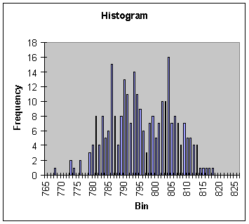
We find an average of 795.6mV with an r.m.s. of 9.9mV. The threshold DACs on the DIALOG chip have a range of 625mV to 1250mV in 8 bits i.e. bins of 2.44mV. This is perfectly compatible with this kind of offset spread.
Subtracting the average offset from each chip one arrives at the following histogram.
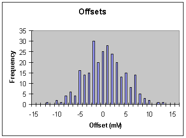
The resulting r.m.s. is 4.243mV. In order to find the true r.m.s. one has to scale this number by sqrt(8/7) arriving at 4.54mV.
We can conclude that the true channel to channel offset variation is about 5mV r.m.s. Using a single DTV per chip this is the variation.
Using individual thresholds the offset variation of the DTV is adding and we arrive a channel to channel variation of 10mV r.m.s. This is the number that the DIALOG chip has to accommodate.