Test Board Details
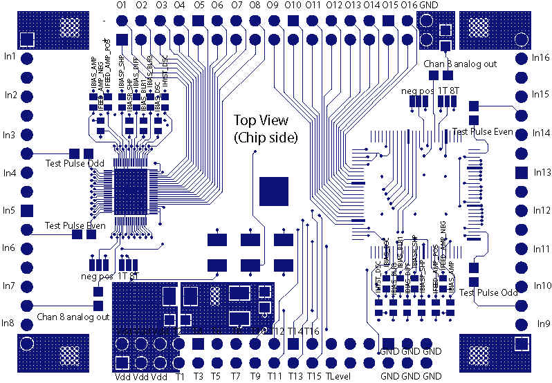
This is the top view of the CARIOCA 10 test board. For printing use the pdf version. The test board circuitry can be found here. One chip (left) is glued on the board with conductive epoxy and bonded directly to the board. The second chip (left) is supposed to go in a package. This way we can evaluate the package effects.
For the first test boards we didn't use a packaged chip but glued the chip to the board as well. This time with an insulating foil. The very long wire bonds represent some kind of worst case package.